Analog-to-Digital Conversion Port on the Digital Lynx Plus
Digital Lynx Plus ADC’s:
The new Digital Lynx Plus (DL+) features up to 16 channels of general-purpose ADC (analog-to-digital conversion). This connector is located on the back of the DL+ and is marked as “analog input” (See figure 1). These 16 channels are high impedance and 18-bit samples. 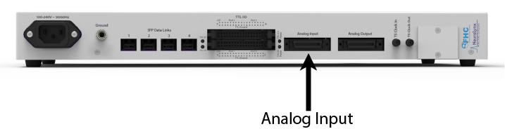
Figure 1: ADC connector of the DL+
The general purpose of these channels is to be used for non-neural inputs. An example of this would be a heartbeat signal, which can be recorded and correlated with the experiment. These ADC inputs are sampled at the same frequency as the HDMI headstage channels (30 kHz). The input voltage range of the ADC channels is +/- 5.12 V. These ports will receive and record any voltage within this range. That is in contrast to the TTL I/O ports which are activated in a high/low pattern by a 5V signal.
More information on these ADC channels can be found on page 29 of the Digital Lynx Plus user manual.
If you have further questions, please contact us at support@neuralynx.com.
Caution – Device for investigational use in laboratory animals or other tests that do not involve human subjects.
Rev. A0