TechTip: How to use stimulation on the DL+ in Cheetah 7
System/Software: DL+, Cheetah
A new feature of Cheetah version 7.0.0 is the ability to stimulate on digital headstages that support stimulation. The Intan RHS2116 chip and upcoming Neuralynx iLynx headstages are two such examples. Stimulation is also supported for Digital IO.
To get into the Stimulation Dialog window, click View > Stimulation (See Figure 1). Please note, this option is only enabled for the Digital Lynx +.
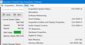
Figure 1: Menu option for Stimulation
Stimulation output on Digital IO (TTLs):
- Hardware required:
- 16-bit Digital IO LED Board connected to either TTL Port 0/1 or TTL Port 2/3.
- Cheetah setup:
- Start Cheetah Data Acquisition Software.
- From the View drop-down menu, select Digital IO Setup… to open the Digital IO Setup dialog.
- Select each of the Input Ports, AcqSystem1_0 Port 00 and Port 01, and click Make Output –> button (See Figure 2).
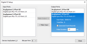
Figure 2: Digital I/O Setup dialog box
4. From the View drop-down menu, select Stimulation to open the Stimulation interface.
Digital Lynx Plus TTL I/O Ports 0/1 Port 0 and Port 1 should be available under Stim Headstages.
C. Demonstrate simple stimulation sequence output (1 train):
-
- Select Digital Lynx Plus TTL I/O Ports 0/1 Port 0 under the Stim Headstages, and click +Add to add a new stimulation sequence, Stim1.
- Under Output Channels, select the odd bits S1, S3, S5 and S7. \
- Under Train1 settings, set Delay (ms) to 0. Leave Train Duration(ms) and Pulse Count to 5.
- Under Pulse settings, leave the Pulse Type as Monophasic, Polarity set to Anode, and Amplitude(uA). (For the Digital I/O, amplitude has no effect on stimulation output since the TTL is either high or low).
- Select ms from the Pulse Resolution drop-down.
- Set the Pulse Frequency (Hz) to 1, and the Phase 1 duration (ms) to 500. (Note the Enter key needs to pressed to update each entry. Changes can be confirmed on the Visualization tab).
- Click the Upload button to upload the stim sequences and click the Stimulate button to trigger the stimulation output to the Digital IO. Observe that the green LEDs are lit 500ms on 500ms off on the Digital IO board.
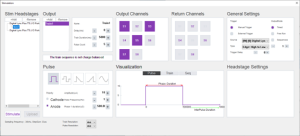
Figure 3: Stim seq 1 setup on Digital IO Port 0
D. Demonstrate multiple stimulation sequences:
-
- Select Digital Lynx Plus TTL I/O Ports 0/1 Port 0 under the Stim Headstages, and click +Add to add a new stimulation sequence, Stim2.
- Select Stim2, and under Output Channels, select the remaining even bits S2, S4, S6 and S8.
- Under Train1 settings, set Delay (ms) to 0. Leave Train Duration (ms) and Pulse Count to 5.
- Under Pulse settings, leave the Pulse Type as Monophasic, and Amplitude (uA).
Select Cathode for the Polarity.
5. Set the Pulse Frequency (Hz) to 1, and the Phase 1 duration (ms) to 500. (Note the Enter key needs to pressed to update each entry. Changes can be confirmed on the Visualization tab).
6. Click the Upload button to upload the two stim sequences and click the Stimulate button to trigger the stimulation output on the Digital IO. Observe that the green and red LEDs alternate on and off for 500ms each demonstrating two stim sequences running simultaneously.
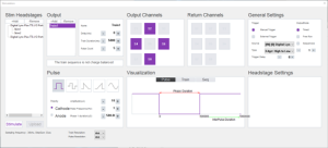
Figure 4: Stim seq 2 setup on Digital IO Port 0
The following can be demonstrated:
- changing different output channels (bits) for each stim sequence,
- changing pulse count,
- changing polarity, pulse frequency, and phase1 durations.
This will require a re-upload of the stim sequences.
E. Demonstrate sequences on multiple device ports:
- Select Digital Lynx Plus TTL I/O Ports 0/1 Port 1 under the Stim Headstages, and +Add two new stimulation sequence, Stim1 and Stim2.
- Select Stim1 of TTL I/O Port 1, and under Output Channels, select the odd bits S1, S3, S5 and S7.
- Under the Train1 settings for Stim1 of Port1, set Delay (ms) to 0. Leave Train Duration (ms) and set the Pulse Count to 10.
- Under Pulse settings, leave the Pulse Type as Monophasic, Polarity set to Anode, and Amplitude (uA).
- Set the Pulse Frequency (Hz) to 2, and the Phase 1 duration (ms) to 250. (Note the Enter key needs to pressed to update each entry. Changes can be confirmed on the Visualization tab).
- Repeat steps 2 through 5 for the Stim2 of TTL I/O Port2 with the following changes.
Set the Output Channels to the even bits S2, S4, S6, S8.
Set the pulse Polarity to the Cathode for alternating green-red LED effect.
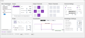
Figure 5: Stim seq 2 setup on Digital IO Port 1
Stimulation output on Intan RHS2116 headstage:
- Hardware required:
- Intan RHS2116 16/32 channel headstage connected to any port on Digital Lynx Plus interface board.
- Cheetah setup:
- Start Cheetah Data Acquisition Software.
- In the Digital Lynx Plus Config dialog, verify thatthe RHS2116 [16/32] channel headstage has been detected and located on the correct Digital Lynx Plus interface port.
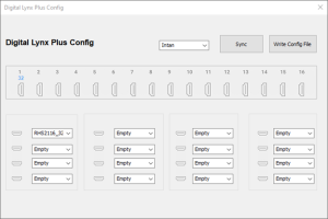
Figure 6: Digital Lynx Plus Config dialog box
3. In Cheetah, from the View drop-down menu, select Stimulation to open the Stimulation interface.
Port [N]: Intan[16/32]Channel should be available under Stim Headstages.
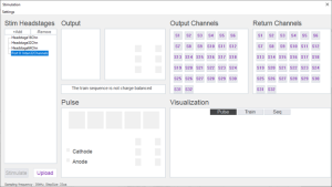
Figure 7: Stimulation Interface dialog box
C. Demonstrate simple stimulation sequence output (1 train):
-
- Select Port 0: Intan[16/32] under the Stim Headstages, and click +Add to add a new stimulation sequence, Stim1.
- Under Output Channels, select the odd channels S1, S3, S5, S7, S9, S11, S13 and S15.
- Under Train1 settings, set Delay (ms) to 0. Leave Train Duration(ms) and Pulse Count to 5.
- Under Pulse settings, select the Pulse Type as Monophasic, set Polarity to Anode, and Amplitude(uA) to 255.
- From the Setttings menu, Select ms from the Pulse Resolution drop-down.
- Set the Pulse Frequency(Hz) to 1, and the Phase 1 duration(ms) to 500. (Note the Enter key needs to pressed to update each entry. Changes can be confirmed on the Visualization tab).
- Click the Upload button to upload the stim sequences and click the Stimulate button to trigger the stimulation output to the Digital IO. Observe that the green leds are lit 500ms on 500ms off on the Digital IO board.
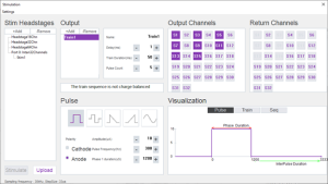
Figure 8: Stim seq 1 setup on Intan RHS2116 32 channels
D. Demonstrate multiple stimulation sequences:
-
- Select Digital Lynx Plus TTL I/O Ports 0/1 Port 0 under the Stim Headstages, and click +Add to add a new stimulation sequence, Stim2.
- Select Stim2, and under Output Channels, select the remaining even bits S2, S4, S6 and S8.
- Under Train1 settings, set Delay (ms) to 0. Leave Train Duration(ms) and Pulse Count to 5.
- Under Pulse settings, leave the Pulse Type as Monophasic, and Amplitude(uA).
Select Cathode for the Polarity.
5. Set the Pulse Frequency(Hz) to 1, and the Phase 1 duration(ms) to 500. (Note the Enter key needs to pressed to update each entry. Changes can be confirmed on the Visualization tab).
6. Click the Upload button to upload the two stim sequences and click the Stimulate button to trigger the stimulation output on the Digital IO. Observe that the green and red leds alternate on and off for 500ms each demonstrating two stim sequences running simultaneously.

Figure 9: Stim seq 2 setup on Digital IO Port 0
The following can be demonstrated:
- changing different output channels (bits) for each stim sequence,
- changing pulse count,
- changing polarity, pulse frequency, and phase1 durations.
This will require a re-upload of the stim sequences.
E. Demonstrate sequences on multiple device ports:
-
- Select Digital Lynx Plus TTL I/O Ports 0/1 Port 1 under the Stim Headstages, and +Add two new stimulation sequence, Stim1 and Stim2.
- Select Stim1 of TTL I/O Port 1, and under Output Channels, select the odd bits S1, S3, S5 and S7.
- Under the Train1 settings for Stim1 of Port1, set Delay (ms) to 0. Leave Train Duration(ms) and set the Pulse Count to 10.
- Under Pulse settings, leave the Pulse Type as Monophasic, Polarity set to Anode, and Amplitude(uA).
- Set the Pulse Frequency(Hz) to 2, and the Phase 1 duration(ms) to 250. (Note the Enter key needs to pressed to update each entry. Changes can be confirmed on the Visualization tab).
- Repeat steps 2 through 5 for the Stim2 of TTL I/O Port2 with the following changes.
Set the Output Channels to the even bits S2, S4, S6, S8.
Set the pulse Polarity to the Cathode for alternating green-red led effect.

Figure 10: Stim seq 2 setup on Digital IO Port 1
The above information and more can be found in the Digital Lynx + user’s guide on pages 17-28.
If you have any questions or concerns, be sure to contact us at support@neuralynx.com and we will be happy to assist you.
Caution – Device for investigational use in laboratory animals or other tests that do not involve human subjects.
Rev. A0