Animal Ground vs. Panel Ground
Neuralynx users are keenly aware that proper reference signal use makes a significant difference in recorded signal quality. This is especially true for microwire multi-single unit Spike recording, where small signals and high electrode impedances make low noise recording difficult. As noise is reduced, results in Spike Sorting (SS3D) greatly improve; conversely, as noise increases, cluster overlap increases, making clusters more ambiguous and difficult to separate. The same issues apply to larger, lower impedance EEG electrodes.
Most Neuralynx headstages have two “ground” connection tether wires that can be used as references: Panel Ground (PGnd) and Animal Ground (AGnd). Initially these grounds seem the same, but the subtle difference between the two can reduce noise.
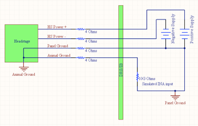
The schematic above shows Animal Ground (AGnd) and Panel Ground (PGnd), as well as the positive and negative supply voltages (HS+ and HS-) connected to the headstage. You can think of PGnd as “Panel Ground” or “Power Ground,” but it is actually the wire on which any difference in the two power supply CURRENTS will return back to the system. (Note: This schematic is only a circuit model for analysis and not the real components.)
Note the following:
- The Panel Ground point represents earth ground for most non-isolated systems at the system;
- The Animal Ground point is not a true ground but represents the potential of the subject animal as a whole;
- The 4 Ohm resistors approximate the resistance of 3 meters of 36Ga tether wire (HS-18, for example);
- The 10 GigaOhm resistor approximates the input impedance of the input stage of the DRS-36 or an Input Board; and
- When you use PGnd as a reference, you are using the signal that is connected to the ground of the system, not the animal.
The headstage circuitry requires power (+/-5V @ ~10mA); the current will flow through both the HS+ and HS- wires and is usually fairly balanced. Due to the dynamics of the input signals and the buffer amplifiers, any differences in the power wire currents must flow back to the system on PGnd.
Because there is current flow (~100 µA) in the PGnd wire and resistance (~4 Ohm) along that wire, there will be a voltage drop from one end of the PGnd wire to the other. This means that the ground voltage at the animal is slightly different than the voltage of the PGnd at the system. This PGnd wire voltage drop can be calculated with Ohm’s Law:
V = I*R or V = 100 µA * 4 Ohm => 400 µV
The AGnd is not connected to the PGnd at the system, except through the input buffer – equivalent of a 10G Ohm resistor. This reduces any current carried by that wire to less than 1pA; therefore we call the AGnd a “non-current-carrying ground.” Since virtually no current flows through this wire, there is also no voltage drop; therefore, at the DRS/IB, the AGnd is a more accurate representation of the true subject voltage potential for signal referencing purposes.
When selecting references for microwires, always use your designated reference electrode first. If for some reason this does not give expected results, try the AGnd or the PGnd but remember the AGnd will probably result in the better of the two.
Several Neuralynx headstages have a buffered AGnd when there is an extra, unused OpAmp on the headstage that will also provide similar results.
Caution – Device for investigational use in laboratory animals or other tests that do not involve human subjects.
Rev. A0